Sunday, December 30, 2012

Snow Globe Render

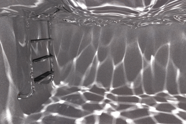
This year, I designed and created the cover image for the Penn Computer Graphics holiday card. I rendered the image in my renderer, Photorealizer:


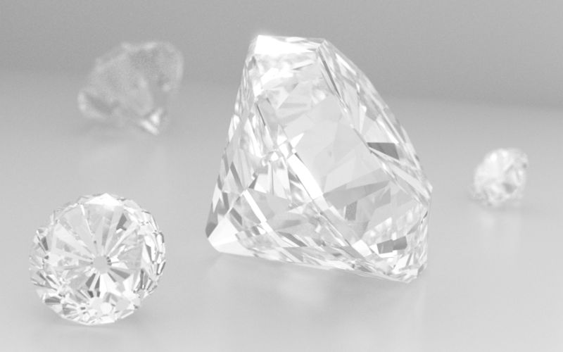
The render features, among other things, global illumination accomplished with Monte Carlo path tracing, path-traced subsurface scattering, a 3D procedural wood texture, reflection from and transmission through rough surfaces, correct behavior at the glass–water (and other) interfaces, an HDR environment map, a spherical light, depth of field, anti-aliasing using a Gaussian reconstruction filter, and an S-shaped transfer curve.

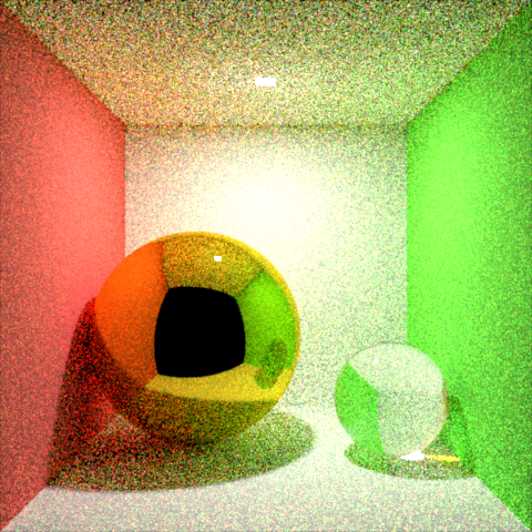
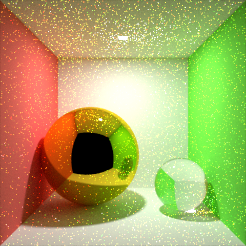
Instead of using neutral white lights like I've often done in the past, I lit this scene with complimentary blue and yellow lights (glacier HDR environment map and small, bright spherical light respectively). This gives the image a more interesting and varied appearance, while keeping the light fairly neutral on the whole. When I started working on the lighting, I started with just the environment map and the image appeared far too blue. Instead of zeroing out the saturation of the environment map or adjusting the white balance of the final image, I decided to add the yellow spherical light to balance it out (inspired by the stage lighting course I took this past semester).

I spent some time tweaking the look of the snowflakes—the shape, the material, and the distribution. I ended up settling on the disc shape, which is actually a squished sphere (not a polygonal object). All of the snowflakes are instances of that same squished sphere. For the material, I made the snowflake diffusely reflect half of the incident light, and diffusely transmit the other half (in other words, a constant BSDF of 1/(2π)). This gives a soft, bright, translucent appearance, while still being very efficient to render (compared to subsurface scattering).

I made some different versions of the image to show how certain features affect the look of the final image:

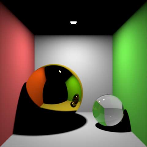
Half-size version, for comparing to the images below.

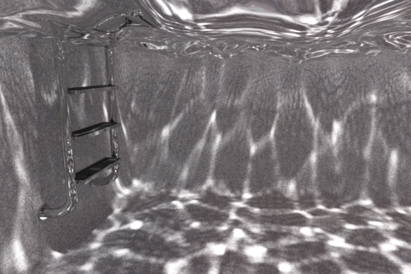
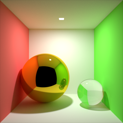
White light version.

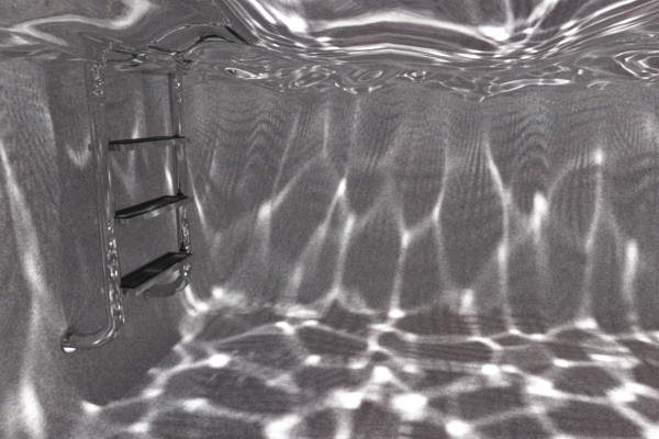
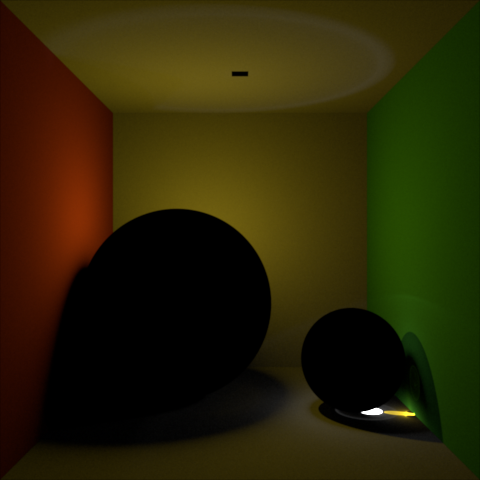
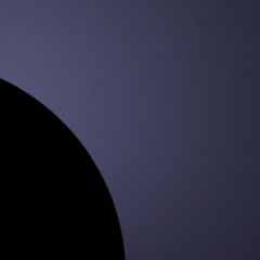
Display-linear version.

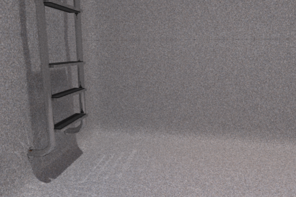
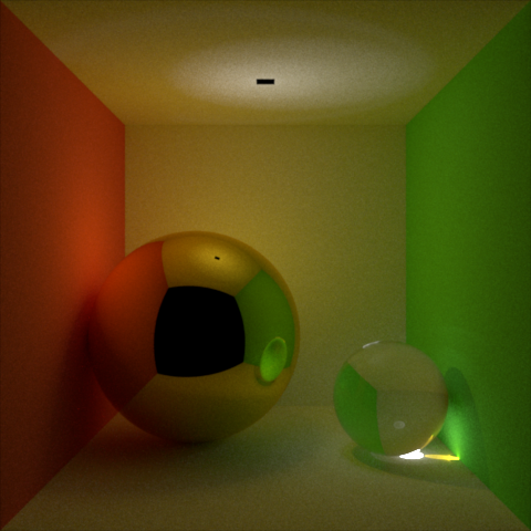
Opaque perfectly diffuse version
(statue, snowflakes, and tablecloth).

For best results, the model needed to be very clean, exact, and physically accurate. I chose to model it using Houdini. I think Houdini is a very well-made piece of software. I really like its node paradigm, procedural nature, and clean user interface. I like having the ability to set parameters using precise numbers, or drive them with scripts, and having the ability to go back and modify parameters in any part of the network at any time.

In addition to using Houdini, I created the LOVE statue shape in Illustrator, and I procedurally added the snowflakes in Photorealizer.

Here are screenshots of the Houdini network and the resulting model:

Houdini network.

Houdini model.

Friday, December 28, 2012

Photon Mapping with HDR Environment Maps

I gave each light source the ability to emit photons, including HDR environment maps, suns, spherical lights, and rectangular lights.

I came up with a way to emit photons from an (infinitely far away) HDR environment map, weight them correctly, and distribute them properly over the entire scene. Below are a few shots of a scene I used to test my system. In this scene, a glass sphere is hovering slightly above a pedestal.

The first two shots below use the Grace Cathedral environment map. This environment map has tiny, bright lights that contribute greatly to the image yet are hardly ever hit when using naive backwards path tracing. I had already implemented HDR environment map importance sampling for direct illumination, but only after implementing photon mapping can I render caustics efficiently as well. My photon mapping system uses the existing importance sampling to select photon emission locations.

Photon mapped indirect illumination, plus direct illumination (using environment map importance sampling).

No indirect illumination (except for ideal specular reflection and refraction of camera rays). Same shot as above except with photon mapping turned off.

The next two shots use the Pisa environment map.

Photon mapped indirect illumination, plus direct illumination.

Pure path tracing. Identical appearance to the image above (except for noise and imperceptible photon mapping bias).

HDR Environment Map Improvements

I made some improvements to my HDR bitmap environment map system to make it more robust, fix a couple little bugs. and make it faster. For testing, I made an 8x4 pixel equirectangular environment map in OpenEXR format, then I used my equirectangular camera to render some pictures of an object using the environment map as a light source. This way, I was able to see the entire environment, what my linear interpolation smoothing was doing, and how the object was being lit.

An enlarged PNG version of the 8x4 pixel OpenEXR environment map.

Here are the final results of my tests, after I made all of the improvements and fixes:

No smoothing. BRDF-based distribution path tracing.

No smoothing. Direct illumination using environment map importance sampling.

Linear interpolation. BRDF-based distribution path tracing.

Linear interpolation. Direct illumination using environment map importance sampling.

You might notice some subtle colored strips on the edges of these images. That's due to anti-aliasing and jittering (of the output image, not the environment map) which, when combined with the equirectangular mapping, cause some samples to end up on the other edges.

Friday, December 21, 2012

Pool Caustics

Here are some renders of the pool scene with a much smaller and brighter light, resulting in cool caustics. I rendered these images with photon mapping—regular path tracing would have taken forever to converge because the light source would have been hit very infrequently (it can't be sampled directly through the water surface). I'm planning to implement photon emission for all lights soon, including the sun and HDR environment maps.

Pool caustics.

Previously, I was not using shading normals for photon tracing, which caused distracting patterns in the caustics (see image below). To fix this (see image above), I made photon tracing use shading normals. For now, I just throw away photons that end up on the wrong side of the surface.

No shading normals.

Before rendering the images above, I was using regular grid tessellation of the water surface, which made the unwanted patterns even worse (see image below). To improve this, I made the grid higher resolution and then reduced the mesh, with triangles distributed to best approximate the surface and give the mesh a more organic appearance (see image above).

When the water surface was a displaced regular grid.

When the water was calm (see image below), the grid patterns disappeared. This helped let me know that the patterns were indeed caused by the tessellation of the water surface, as opposed to a random number issue or something else.

Calm water. Same exposure and everything else.

Thursday, December 20, 2012

Latitude Longitude Shot

I added the new cameras from my sky renderer to Photorealizer, and rendered a new picture of the pool scene using the latitude longitude camera (as always, click the image to view it at full size):

The swimming pool scene shot with my new latitude longitude camera.

(The little nick in the corner near the ladder is a tiny geometry problem, not a renderer problem.)

After saving that image in high dynamic range OpenEXR format, I used it as a latitude longitude environment map to render this image:

Water droplets lit by the high dynamic range version of the above image.

For the PNG version of the latitude longitude shot at the top, I had Photorealizer apply an S-shaped transfer curve to increase the contrast and saturation. Here's what it would have looked like without that:

Display linear.

Pretty washed out.

And here's an earlier version of the render, with shading normals disabled, which resulted in some ugly tessellation artifacts on the water surface:

No shading normals.

Modifying the normal can cause problems such as incident, reflected, or refracted directions ending up on the wrong side of the surface. These types of things can cause light leakage through surfaces or black spots. To avoid problems like these, I came up with a way to strategically modify the problematic directions.

Thanks for looking at my blog!

Wednesday, December 19, 2012

Transmitted Radiance

Intuitively, when light is refracted, the same amount of light is squeezed into a smaller solid angle, or spread into a bigger one, which results in an increase or decrease respectively of radiance along each ray (since radiance is flux per unit projected area per unit solid angle). As worded on Wikipedia, "the radiance divided by the index of refraction squared is invariant in geometric optics." For light traveling from medium i (incident) into medium t (transmitted), this invariant can be written as Lt / ηt2 = Li / ηi2 (where L is radiance and η is index of refraction), which implies that Lt = Li * (ηt / ηi)2. Thus, in a ray tracer, when a ray is refracted across an interface, we need to scale the radiance that it is carrying by (ηt / ηi)2.

An image from Eric Veach's thesis.

I had never thought about this until I read about it recently in Eric Veach's thesis. In section 5.2, Veach explains why BSDFs are non-symmetric when refraction is involved, and how to correct for this (see the thesis for a full explanation, and for a lot more great stuff). After reading Veach's explanation, I implemented a correction factor in my renderer. You can see some before and after images below.

For photon mapping, the correction factor is not needed, because photons carry flux (or power) instead of radiance, and because computing irradiance based on a photon map involves computing the photon density, which is naturally higher where the same number of photons have been squeezed into a smaller area.

In cases where light enters and then later exits a medium (or vice versa), the multipliers cancel each other out, which hides the problem. But in other cases, the problem can be very apparent. In the underwater images below, you can see that the path tracing and photon mapping versions do not match until the transmitted radiance fix is made. The path tracing image without the fix appears much too dark. If I had instead put the light under the water and taken a picture on the air side (the opposite situation), the scene would have appeared too bright rather than too dark.

Path tracing before transmitted radiance fix.

Photon mapping before transmitted radiance fix.

Path tracing after transmitted radiance fix.

Photon mapping after transmitted radiance fix.

There are some artifacts in these renders due to the lack of shading normals (Phong shading; smoothing by interpolating vertex normals across faces). My photon mapping implementation doesn't currently support shading normals, so I disabled them for these renders in order to make the best comparisons possible. Shading normals can also add bias to renders, but they can also make images look much nicer when used appropriately and carefully.

There are also some artifacts due to problems with the scene, which I've since fixed. (In my next post I'll post a shot of the scene from above the water, cleaned up, and with shading normals.) I found the ladder on SketchUp, and then modified it in Maya (but I probably should have just made one from scratch for maximum control and to make it as clean as possible), and modeled the rest of the scene myself, mostly in Houdini. Houdini is nice for certain kinds of procedural modeling, and it makes it really easy to go back and modify anything.

Usually (depending on the settings), upon the first diffuse (or glossy) bounce, I shoot multiple rays. If the ray from the camera encounters a refractive surface before the first diffuse bounce, I split the ray, and then split the number of rays allocated to the first diffuse bounce proportionally between the reflected and refracted paths (deeper interactions with refractive surfaces use Russian Roulette to select between reflection and refraction to avoid excessive branching). As I was making these renders I caught and fixed a importance sampling bug where, after total internal reflection, the number of rays allocated to both paths was just one, instead of a representative fraction of the total. Since there is a lot of total internal reflection visible on the bottom of the water surface in this shot, this bug was causing the reflection of the pool interior to converge much more slowly than the direct view of the pool interior.

Tuesday, December 18, 2012

Architecture

To give you an idea of how the code behind Photorealizer is organized, here's a list of all of the C++ classes that I've written (updated January 25, 2013), with subclasses nested below their superclass. (A few of these things are actually class templates or namespaces with functions in them, but they might as well be classes.)


AdaptiveSampler
AdaptiveSamplerSample
Aperture
    PinholeAperture
    WideAperture
AxisAlignedBoundingBox
BasicMath
Bitmap

    LDRBitmap
    HDRBitmap
BitmapTextureMapData

BoundingSphere
BSDF

    CookTorranceBRDF
    LambertBRDF
    LambertBTDF

    ModifiedPhongBRDF
    OrenNayarBRDF
    SpecularMicrofacetBSDF 
BSDFSample
BSDFWeight
BVH
BVHNode
Camera

    AngularFisheyeCamera
    LatitudeLongitudeCamera 
    RegularCamera
CameraSample
Color
ColorProfile

    PowerLawColorProfile
    SRGBColorProfile
ColorRamp
ColorTransform

    BlackAndWhiteColorTransform
    BlackLevelColorTransform

    ColorBalanceColorTransform
    CyanColorTransform
    RedColorTransform 
    RollOffContrastColorTransform
    SinusoidalContrastColorTransform
CustomOutput
Distribution1D
Distribution1DSample
Distribution2D
Distribution2DSample
FileNameUtils
FinalGatheringPoint
FinalGatheringSample
FinalGatheringSampler
Fresnel
HaltonSequence
ImprovedPerlinNoise
ImprovedPerlinNoiseFunctions
IndexOfRefraction
Interpolator
Intersection
IntersectionExtras
IrradianceSample
KDTree
KDTreeNode
KDTreePoint
Light

    DirectionalLight
    EnvironmentMap
        CIEOvercastSky
        ColorEnvironmentMap
        GradientEnvironmentMap
        HDREnvironmentMap
            FisheyeHDREnvironmentMap
            EquirectangularHDREnvironmentMap 
    RectangularAreaLight
    SphericalLight
    Sun
LightIntersection
LightPhoton
LightSample
LinearAlgebra
Main
MainWindow
Medium
MersenneTwister
Motion
MultipleScattering
MultipleScatteringOctree
MultipleScatteringOctreeNode
OpenEXRImage
OpenEXRStuff
PathTracer
PhaseFunction

    HenyeyGreensteinPhaseFunction
    IsotropicPhaseFunction
Photon
    IrradiancePhoton
PNGWriter
PointMaterial

    Material
Rasterizer
Ray

    AxisAlignedBoundingBoxRay
ReconstructionFilter

    BoxFilter
    GaussianFilter
    TriangleFilter
ReflectionRefraction
RenderDispatcher
SceneObject
    Primitive
        AnyPolygon
        Cube
        Cylinder
        HeightField
        InfiniteGroundPlane 
        Metaballs
        Sphere
    TransformableSceneObject
        SceneObjectContainer
            Model
            Pedestal
            Scene
                HardCodedScene
SellmeierCoefficients
Settings

    HardCodedSettings
Shutter
    InstantaneousShutter
SpatialGridHashTable

    SimpleIntersection
SpatialGridHashTablePoint
SpecularMicrofacetDistribution

    BeckmanDistribution
    GGXDistribution
Stopwatch
StringUtils
Test
TextureMap
    TextureMap2D

        BitmapTextureMap
        CheckeredTexture
     TextureMap3D
        MarbleTexture
        WoodTexture
Triangulator
Vertex
    VertexWithNormal
    VertexWithNormalAndUV
    VertexWithUV
Volumetric
VolumetricIntersection
Voxel
VoxelBuffer


I wrote all of that code (and designed the architecture) from scratch, except for the following minor pieces: a function for efficient ray–box intersection (I had previously written my own, but it wasn't as efficient), improved Perlin noise (I converted the Java code to C++; I've implemented Perlin noise before, but not the improved version), a few of the functions in my custom linear algebra library (I previously used a basic linear algebra library found here), a basic UI based on this Qt image viewer example.

In addition to the classes listed above, I also utilize three libraries for loading and saving bitmap images (OpenEXR, stb_image, and libpng), as well as Qt for the GUI (used to use Cocoa on Mac), OpenMP for multithreading (used to use Grand Central Dispatch on Mac), and of course C++ (including some new TR1 and C++11 features).

I try to write code that is clean, descriptive, and readable. Here are a couple relevant quotes that I like:

"Any fool can write code that a computer can understand. Good programmers write code that humans can understand." ~Martin Fowler

"One of the miseries of life is that everybody names things a little bit wrong, and so it makes everything a little harder to understand in the world than it would be if it were named differently." ~Richard Feynman

Thursday, November 15, 2012

Sky Renderer

I'm currently working on a physically-based sky renderer.

To create it, I've written a spectral rendering system, modeled the atmosphere, simulated light transport in the atmosphere, and more. To make the output as realistic as possible even when the sun is below the horizon, I simulate multiple scattering, I include preferential absorption by ozone (which gives the twilight sky its blue color), and I use unbiased distance sampling. To make the renderer as efficient as possible, I sample the sun directly.

For lots of details, check out my project blog at skyrenderer.blogspot.com.

A fisheye shot of twilight, rendered in my new sky renderer. The dark blue area at the bottom is the shadow of the Earth which is cast into the atmosphere when the sun is below the horizon.

Thursday, August 30, 2012

Photon Mapping Revamp

I revamped my photon mapping system a few weeks ago. The results are now radiometrically correct, converging to the same image as path tracing. I currently support Lambertian diffuse reflection (for indirect diffuse) as well as ideal specular reflection and refraction (for caustics). I took some inspiration from progressive photon mapping, storing all photons (diffuse and caustic) in a single photon map, visualizing the photon map directly (instead of doing final gathering), and doing multiple passes and progressively improving the image. Currently, I'm using a fixed search radius for photon lookups (and my own templatized k-d tree), and just starting with a very small radius so that the results are visually indistinguishable from path tracing; I could easily modify the system to use an increasingly smaller search radius. Because I'm doing multiple passes, memory isn't an issue—I can trace any number of photons in each pass, which affects the rate of convergence, but not the final result.

My old photon system had some significant limitations and flaws. When I started working on my ray tracer over two years ago, I thought photon mapping would be the best way to achieve realistic lighting, but I knew very little about rendering and radiometry at the time, so while I made good progress on it, I was not able to implement everything correctly or efficiently, and I eventually got stuck. Now I have a better understanding of that stuff, so I revisited photon mapping, partially for the fun and challenge, and partially to produce pictures that I couldn't produce before—pictures of situations that are difficult for path tracing to handle, especially caustics from small, bright lights.

I plan to make my photon mapping system more powerful in the future, and to render some pretty images containing fancy caustics. The scene I rendered below is not the most attractive, but it's good for illustrative purposes.

Photon mapping used for indirect diffuse and caustics.
Path tracing reference. Looks identical to the photon mapping version above, except it's still a little noisier than the photon mapping version. I let this render for much longer than the photon mapping version. The caustics took forever to smooth out.
Path tracing with photon-mapped caustics.
Direct lighting only (plus specular reflection and refraction of camera rays). In the top image above, all of the rest of the light comes from the photon map.
Path tracing with no caustics. Compare to the full versions above to see how much contribution caustics have on this image. Also notice the lack of noise, even though this was rendered in much less time than the full path tracing image above.
Caustics only (created using photon mapping).
Caustics, plus diffuse and specular reflection and refraction. This is what the scene looks scene looks like if lit only by the caustics in the image above. Notice, on the ceiling, the caustic of a caustic; the hot spot under the glass ball is projected back through the ball and onto the ceiling.
What the top photon mapping image looked like after the first pass.
What the path tracing reference looked like after the first pass (which took quite a bit longer than one pass of the photon mapping version). The fireflies are the caustics.
Subtle artifacts (isolated here) from a pseudo-random number generator issue. Months ago I changed my PRNG to Mersenne Twister, but I switched it back to rand() when I put the program on my Mac laptop to work on it on it over the summer, because the Mersenne Twister stuff didn't port without effort. It took me a while to figure out what was causing these artifacts.
Problem fixed by switching Mac version to use Mersenne Twister.

Saturday, May 26, 2012

First Images with Dispersion

I recently implemented dispersion in Photorealizer using some of the ideas I described in a previous post. I'm using the Sellmeier equation along with material-specific Sellmeier coefficients to determine the refractive index of the material at any given wavelength. Right now I'm only tracing three specific wavelengths, one for each of red, green, and blue. Because the sRGB primaries are not spectral colors, I simply chose nearby spectral colors, keeping things simple for now.

Here is a render of diamonds with dispersion. The color in this image comes entirely from dispersion.

Diamonds with dispersion. Click to view full size.

Here's the same render, before bloom was applied (my bloom is a post-process; the renderer applies it to the completed image):

Same render as above, but without bloom.

Here is a similar scene rendered with and without dispersion, for comparison. The color in these images comes entirely from dispersion as well. The effect of dispersion is a little more subtle in these images than in the ones above.

Dispersion. Bloom.
No dispersion. Bloom.
Dispersion. No bloom.
No dispersion. No bloom.

At some point I'd like to develop a more robust spectral rendering framework, so I can more accurately render dispersion, as well as interference, diffraction, and other wavelength-dependent effects for which three wavelengths (R, G, and B) are insufficient.

Here are a few earlier dispersion renders: